
2021-22
Independent design and build of an electrochemical test vehicle to collect data validating flow field performance
As the lead mechanical designer of the air cathode assembly, I was responsible for designing the flow field: the flow path geometry that distributes air uniformly across the entirety of our meter tall electrode area. I was also responsible for validating this design, so I created a test vehicle to do so.
Key features of the final design #3 - full SolidWorks assembly
To design an air flow field, before I did any real-world prototyping, I worked with an external consultant to run CFD (computational fluid dynamics) simulations to quickly iterate on geometry without needing to build anything. I then drew a rough draft in Solidworks Flow Simulation and worked with the same consultant to determine a higher fidelity map of expected flow. We iterated in this way until the flow field looks good on paper and needs to be validated electrochemically.
Design #1
The first design I built was a sandwich of clear acrylic with the flow field inside that I could run a set volume flow rate through with resealable holes through which one could stick incense through to visualize smoke flow velocity and directionality. I measured velocity through an app called Tracker, which takes video input, a user-inputted distance measurement and markers per frame to calculate velocity.
This design had a few flaws. It was difficult to maintain a perfect seal around the perimeter and the smoke tracking had to be done manually, which was a tedious process. We decided that ultimately, the thing we were trying to measure was cathode performance, and after consulting with various subject matter experts at Form, learned that the effects of the rest of the cell chemistry should be significant enough that any cathode performance should be measured in an electrochemical cell.
Design #2
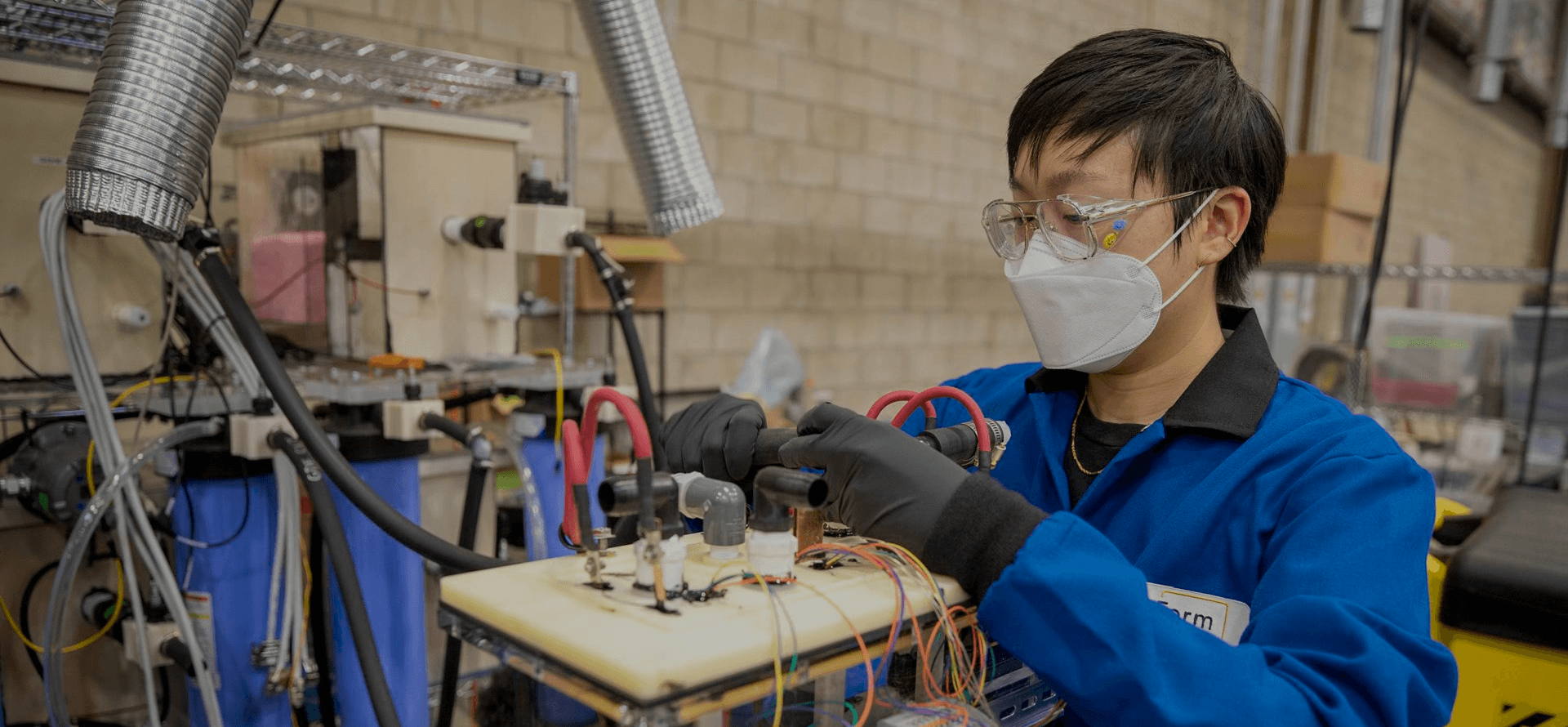
In this design, I made an acrylic vessel to contain the cell chemistry, a sensor wire array sealed in epoxy with 15 measurement points, and tried to make a modular assembly where the only thing that would need to get swapped out between tests was the flow field subassembly. This fixture made a celebrity cameo in this NPR article about Form Energy.
This design also had a few flaws. I tried to protect the copper busbars with an epoxy and had issues mid-test with corrosion from the electrolyte reaching the copper, which skewed the data. I also constructed the vessel myself, and had to repair a couple pinhole leaks due to not sufficiently polishing the edges of the acrylic before welding it together. It was also difficult to get the full picture of the flow field due to the sparse spacing of sensor wires, and unwieldy to swap out the flow field assembly because of the height needed to lift it out of the vessel.
Design 1: big acrylic sandwich
Design 1: smoke velocity tracking

Installing Design #2
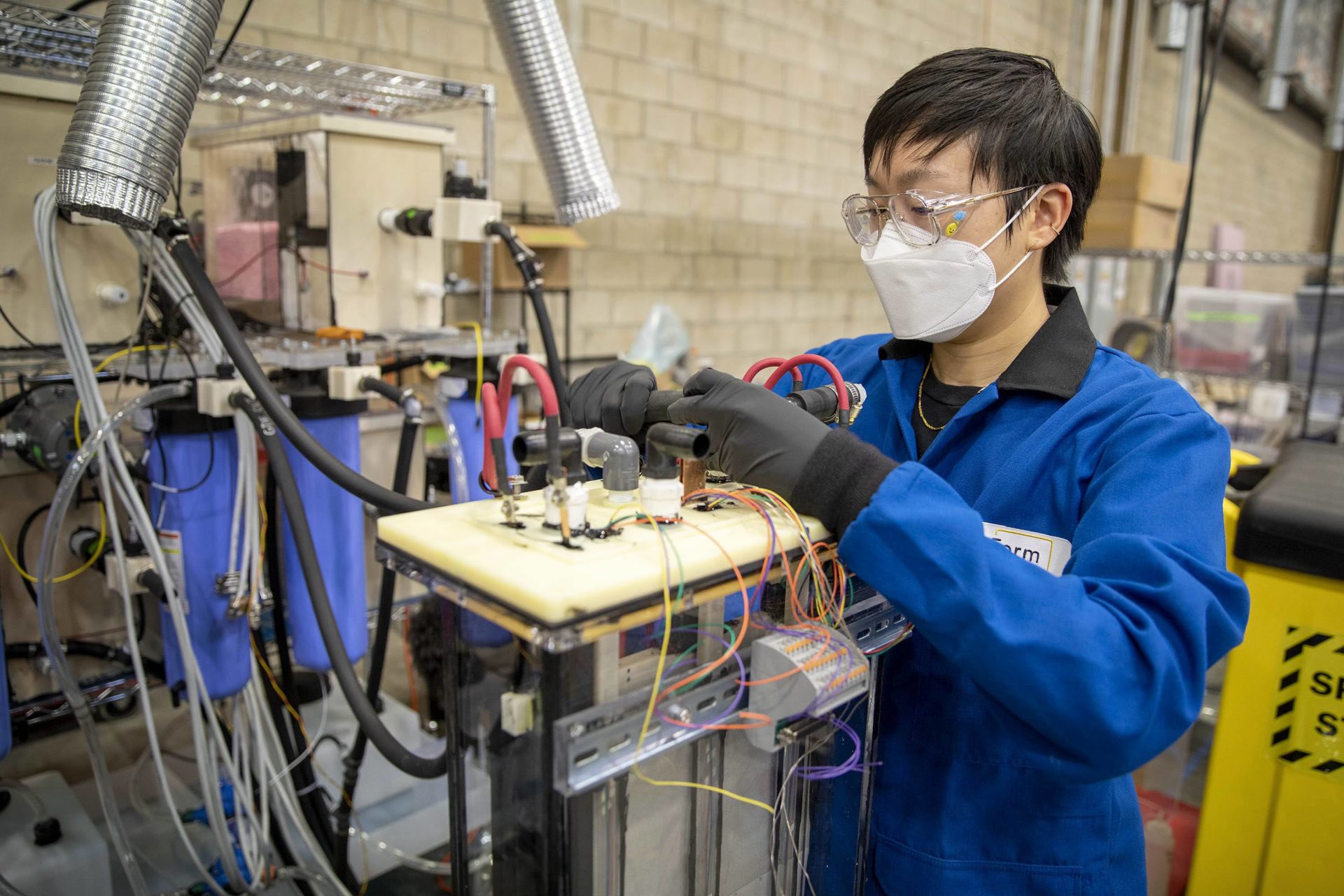
Installing Design #2 - hooking up air connections
Design #3
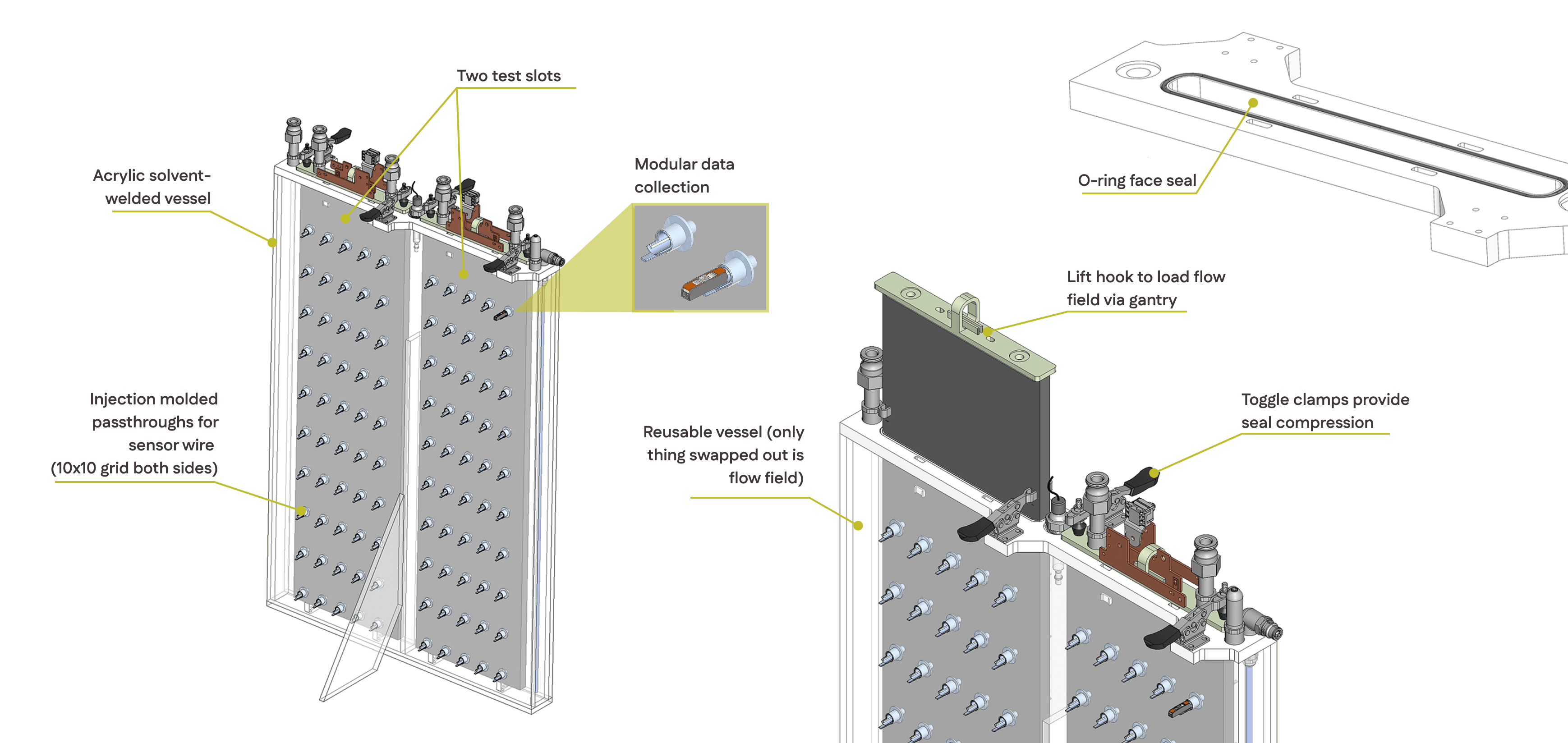
I delivered this design when I left Form, and it continued to be used through a year after I left - I haven't checked in since then! One constraint I ran into in the previous design is that it was difficult to get testing real estate on our limited full cell test stands - the infrastructure that cycles the cells and collects data. I wanted to maximize space in this design to make it possible to test multiple flow fields at a time for faster iterations. Some details are redacted - the flow field assembly is pictured as a black box.

idea for external wiring

multiple flow fields in the same test
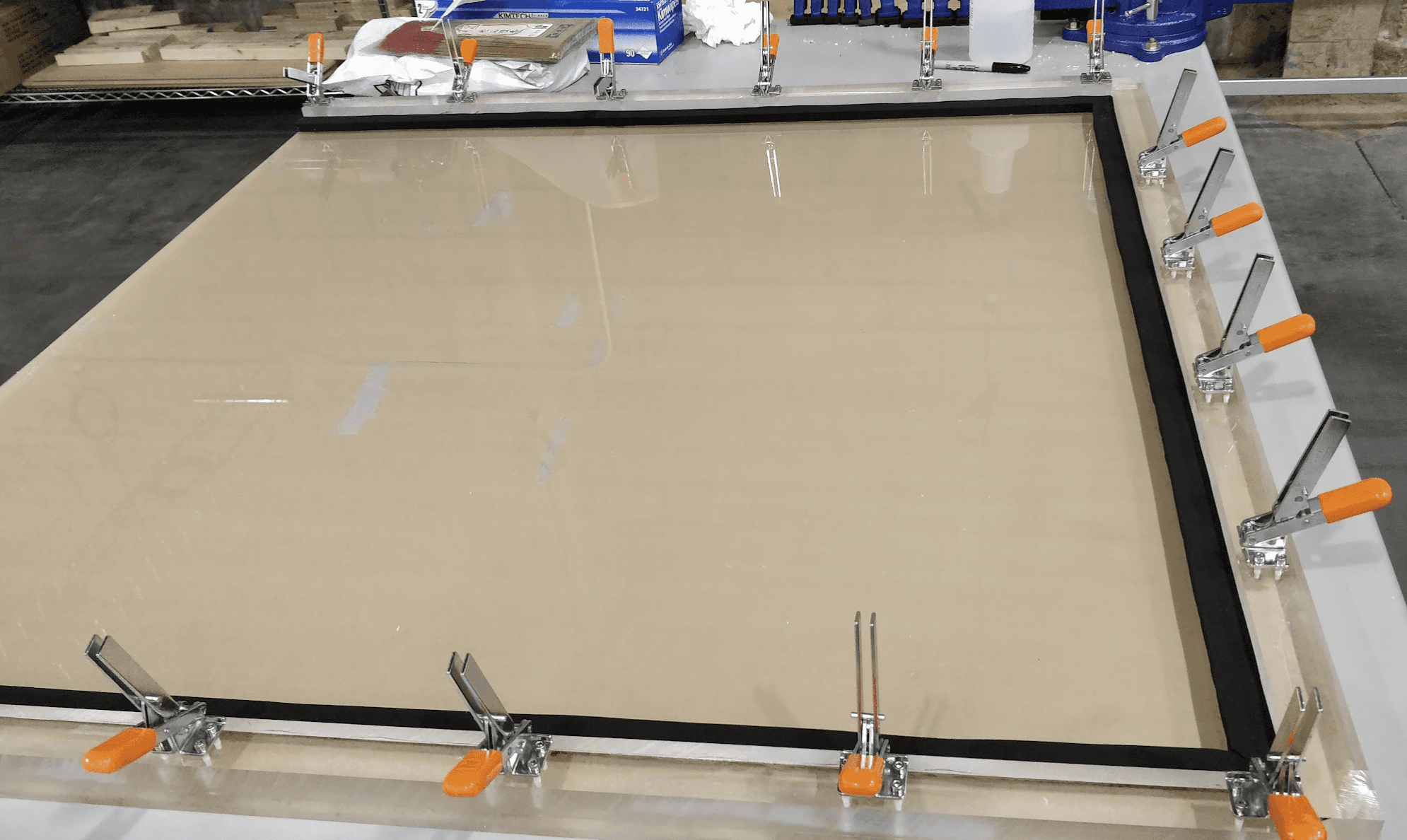
Sealing brainstorming
Wall deformation under hydrostatic pressure, a.k.a. evil avocados
Ensuring lid doesn't fail under clamp force required to maintain o-ring face seal
For the measurement system, I designed a grid where all the wiring back to the Data Acquisition System (DAQ) was routed outside of the vessel (so all the wires wouldn't have to be encased in epoxy across their entire length up to the lid as to avoid electrolyte corrosion). Each measurement sensor was connected to an external wire via a lever nut to maintain modularity (the user can decide which points to collect measurements from).
1. Epoxy gets poured into injection molded caps that are solvent welded to acrylic sheet
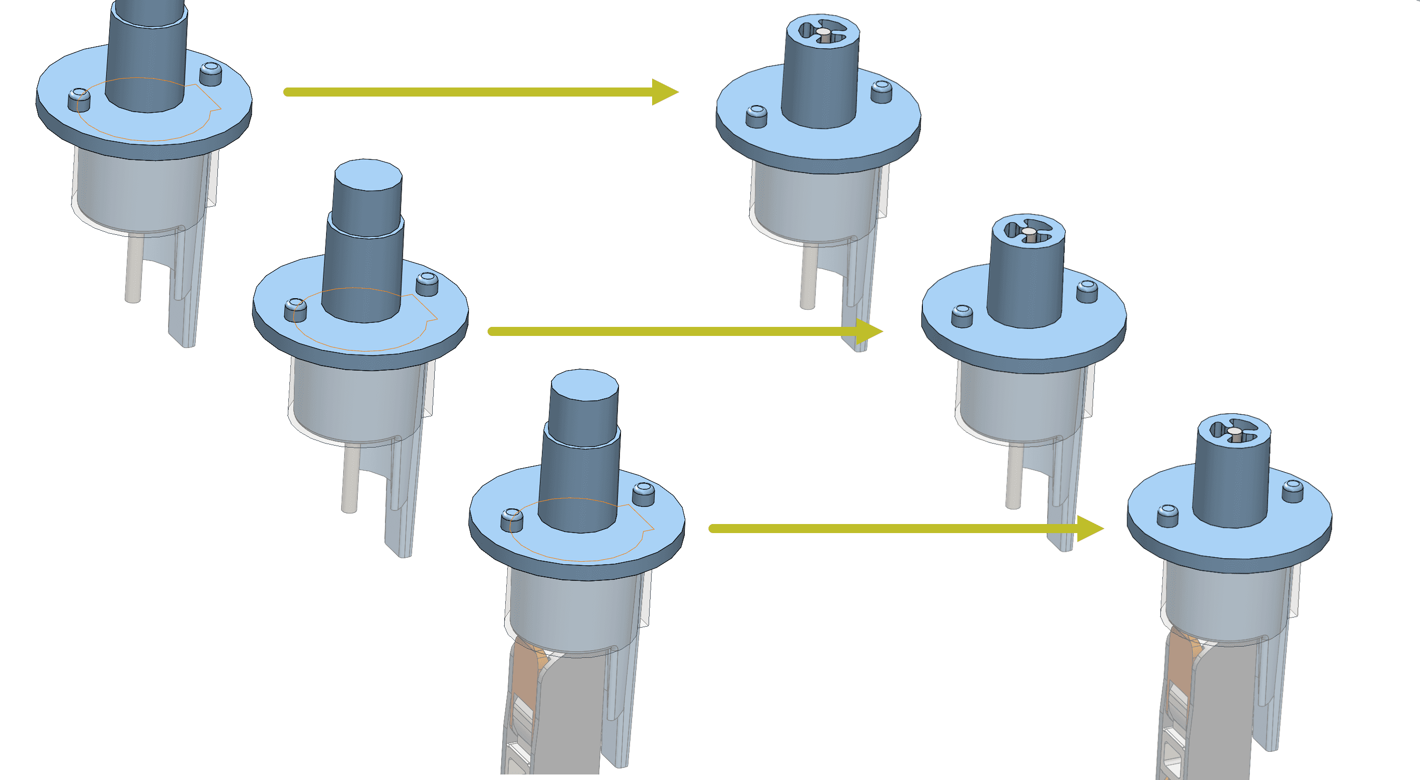
2. After cure, plate inverted and caps cut off to reveal potted sensor wire cross section
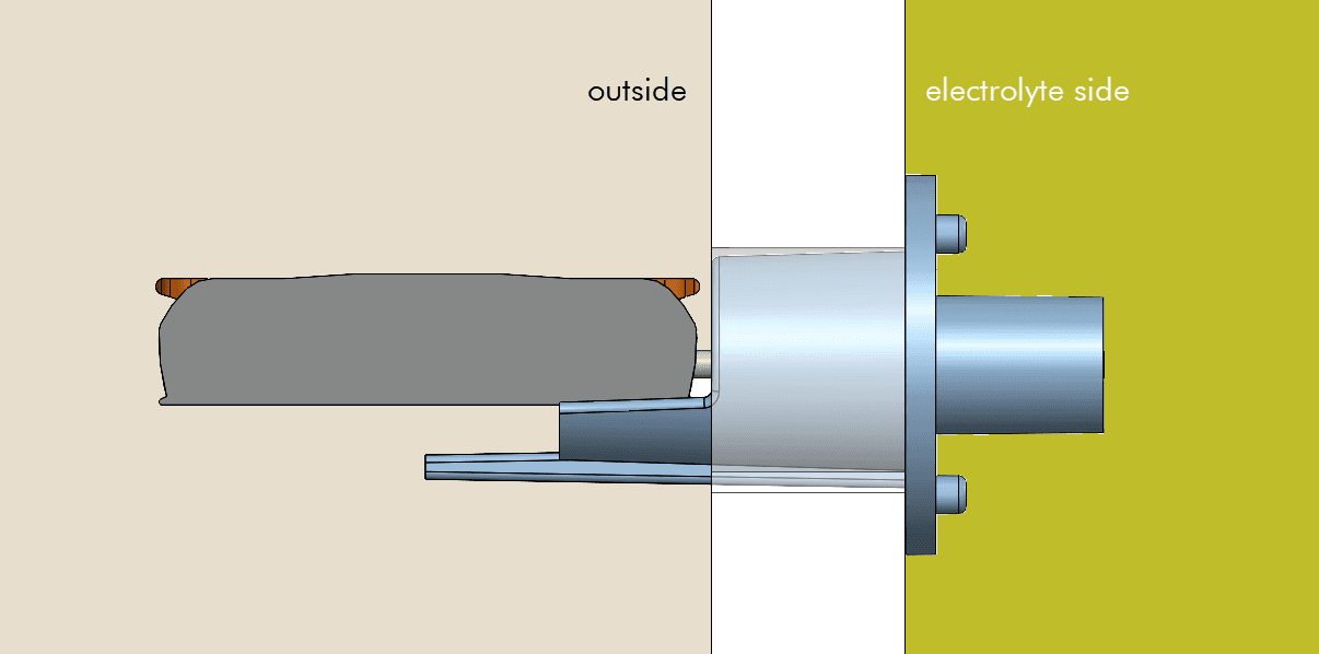
3. As installed through the vessel wall - lever nut gets connected back to DAQ
Here is the overall assembly, repeated from the top of the page.
Key features of the final design #3 - full SolidWorks assembly
Acknowledgements
Thanks to Angel, Joe, Nick, and Kathy for being my ME mentors and thanks to Meghan, Danielle, and Vlad of the cathode team for schooling me in science.
kalinais@stanford.edu
messenger pigeon alternatives